


- Description
- Reviews
- FAQs
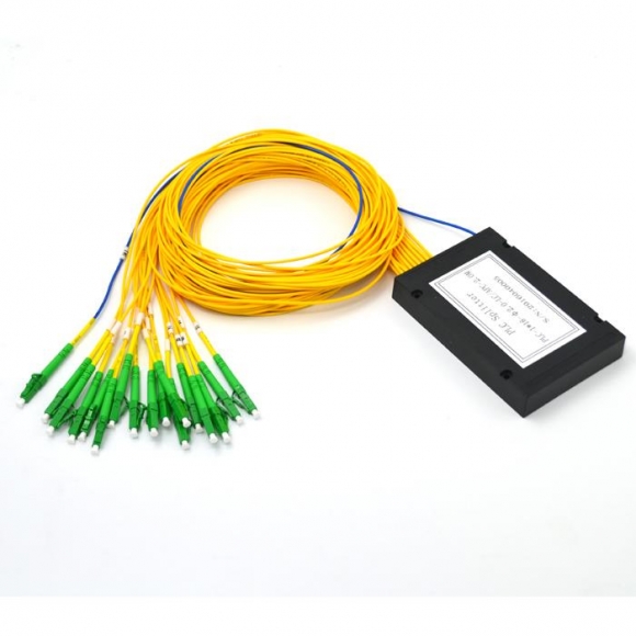
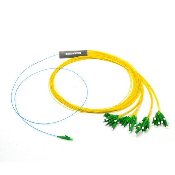
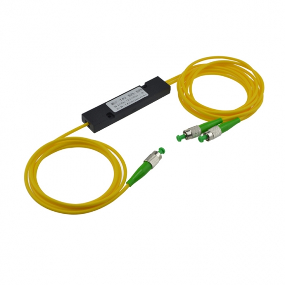
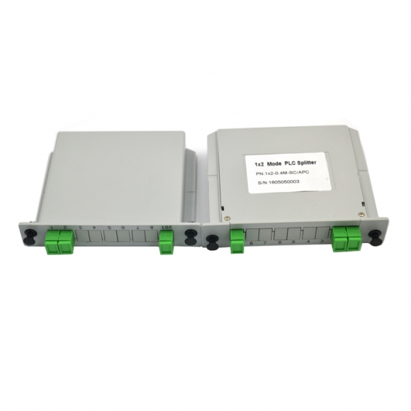
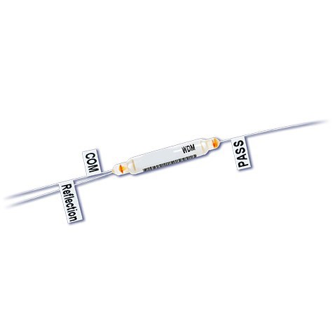
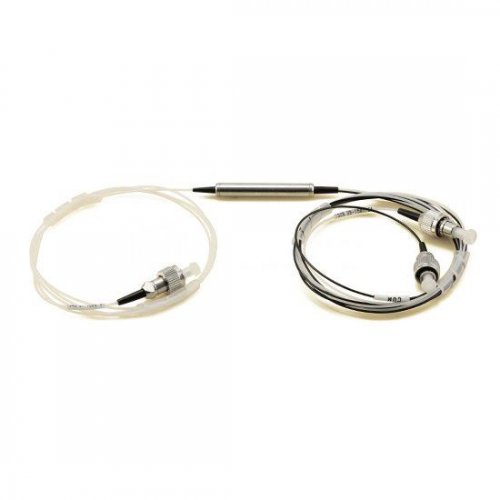
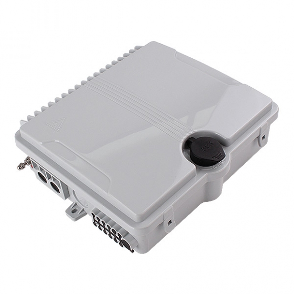
8+1CH Minni CWDM MuxDemux-lgx box
Features
- Low Insertion Loss
- Wide Broadband
- Low Insertion Loss
- Wide Broadband
- High Isolation
- High Stability and Reliability
- No Glue light path
Area of Applications
- MAN (metropolitan area network)
- CATV System
- Network Connection
- Data system
Performance Index
| Parameters | 1×2 | 1×4 | 1×8 | 1×16 | |
| Center Wavelength (nm) | ITU, ITU+1 | ||||
| Passband (nm) | ITU±6.5 | ||||
| Operating Wavelength (nm) | 1460-1620 or 1260-1620 | ||||
| Channel Space (nm) | 20 | ||||
| Fiber Type | SMF-XB G657A | ||||
| IL (dB) (P/A Grade) | 0.7/1.0 | 1.4/1.7 | 2.0/2.5 | 3.5/4.0 | |
| Isolation (dB) | Adjacent Channel | 30 | |||
| Non-Adjacent Channel | 50 | ||||
| Ripple (dB) | 0.3 | 0.4 | 0.5 | 0.5 | |
| PDL (dB) | 0.2 | ||||
| PMD (ps) | 0.1 | ||||
| RL (dB) | 45 | ||||
| Directivity (dB) | 50 | ||||
| Maximum Optical Power (mw) | 500 | ||||
| Operating Temperature (℃) | -40-85 | ||||
| Storage Temperature (℃) | -40-85 | ||||
| BOX Package (mm) | 58*30*9.6 | ||||
Ordering information
| WDMM | xx | x | x | xx | xx | xx | x | x | x |
| Port Configuration | WDM Type | Module Type | Initail Wavelength | Package Type | Fiber Typoe | Output Fiber Lebgth | Input Connector | Output Connector | |
| WDM | 01=1*1 | C=CWDM 1460-1620 | M=Mux | 27=1270nm | PS=100*80*10 | 9=900um loose tube | 10=1.0m | 0=None | 0=None |
| M=Module | 02=1*2 | Q=CWDM 1260-1620 | D=Demux | 31=1310nm | PL=140*115*18 | 2=2.0mm loose tube | 15=1.5m | 1=FC/UPC | 1=FC/UPC |
| 03=1*3 | 48=1480nm | LX=LGX box metal | 3=3.0mm loose tube | 20=2.0m | 2=FC/APC | 2=FC/APC | |||
| …… | 49=1490nm | 19=19”1U | 3=SC/UPC | 3=SC/UPC | |||||
| 16=1*16 | Mini box | 4=SC/APC | 4=SC/APC | ||||||
| …… | 5=LC/UPC | 5=LC/UPC | |||||||
| 32=1*32 | 6=LC/APC | 6=LC/APC | |||||||
| xx= Customized | xx= Customized | xx= Customized | x= Customized | x= Customized | x= Customized |
https://sfiberoptic.com/product/1×8-cwdm/
Wavelength-division multiplexing
In fiber-optic communications, wavelength-division multiplexing (WDM) is a technology which multiplexes a number of optical carrier signals onto a single optical fiber by using different wavelengths (i.e., colors) of laser light This technique enables bidirectional communications over one strand of fiber, as well as multiplication of capacity.
DWDM and CWDM explained
The two key WDM technologies are Coarse Wavelength Division Multiplexing, CWDM and Dense Wavelength Division Multiplexing, DWDM. Which solution is best suited to a given environment depends on the network and user requirements.
CWDM
CWDM supports up to 18 wavelength channels transmitted through a fiber at the same time. To achieve this, the different wavelengths of each channel are 20nm apart. DWDM, supports up to 80 simultaneous wavelength channels, with each of the channels only 0.8nm apart. CWDM technology offers a convenient and cost-efficient solution for shorter distances of up to 70 kilometers. For distances between 40 and 70 kilometers, CWDM tends to be limited to supporting eight channels.
DWDM
Unlike CWDM, DWDM connections can be amplified and can, therefore, be used for transmitting data much longer distances.
Coarse WDM (CWDM)
Originally, the term coarse wavelength division multiplexing (CWDM) was fairly generic and described a number of different channel configurations. In general, the choice of channel spacings and frequency in these configurations precluded the use of erbium doped fiber amplifiers (EDFAs). Prior to the relatively recent ITU standardization of the term, one common definition for CWDM was two or more signals multiplexed onto a single fiber, with one signal in the 1550 nm band and the other in the 1310 nm band.
CWDM Applications
- CWDM is being used in cable television networks, where different wavelengths are used for the downstream and upstream signals. In these systems, the wavelengths used are often widely separated. For example, the downstream signal might be at 1310 nm while the upstream signal is at 1550 nm.[citation needed]
- Some GBIC and small form factor pluggable (SFP) transceivers utilize standardized CWDM wavelengths. GBIC and SFP CWDM optics allow a legacy switch system to be “converted” to enable wavelength multiplexed transport over a fiber by selecting compatible transceiver wavelengths for use with an inexpensive passive optical multiplexing device.
- The 10GBASE-LX4 10 Gbit/s physical layer standard is an example of a CWDM system in which four wavelengths near 1310 nm, each carrying a 3.125 gigabit-per-second (Gbit/s) data stream, are used to carry 10 Gbit/s of aggregate data.
- Passive CWDM is an implementation of CWDM that uses no electrical power. It separates the wavelengths using passive optical components such as bandpass filters and prisms. Many manufacturers are promoting
- passive CWDM to deploy fiber to the home.
Dense WDM(DWDM)
Dense wavelength division multiplexing (DWDM) refers originally to optical signals multiplexed within the 1550 nm band so as to leverage the capabilities (and cost) of erbium doped fiber amplifiers (EDFAs), which are effective for wavelengths between approximately 1525–1565 nm (C band), or 1570–1610 nm (L band). EDFAs were originally developed to replace SONET/SDH optical-electrical-optical (OEO) regenerators, which they have made practically obsolete. EDFAs can amplify any optical signal in their operating range, regardless of the modulated bit rate. In terms of multi-wavelength signals, so long as the EDFA has enough pump energy available to it, it can amplify as many optical signals as can be multiplexed into its amplification band (though signal densities are limited by choice of modulation format). EDFAs therefore allow a single-channel optical link to be upgraded in bit rate by replacing only equipment at the ends of the link, while retaining the existing EDFA or series of EDFAs through a long haul route. Furthermore, single-wavelength links using EDFAs can similarly be upgraded to WDM links at reasonable cost. The EDFA’s cost is thus leveraged across as many channels as can be multiplexed into the 1550 nm band.
DWDM Systems
At this stage, a basic DWDM system contains several main components:
WDM multiplexer for DWDM communications
A DWDM terminal multiplexer. The terminal multiplexer contains a wavelength-converting transponder for each data signal, an optical multiplexer and where necessary an optical amplifier (EDFA). Each wavelength-converting transponder receives an optical data signal from the client-layer, such as Synchronous optical networking [SONET /SDH] or another type of data signal, converts this signal into the electrical domain and re-transmits the signal at a specific wavelength using a 1,550 nm band laser. These data signals are then combined together into a multi-wavelength optical signal using an optical multiplexer, for transmission over a single fiber (e.g., SMF-28 fiber). The terminal multiplexer may or may not also include a local transmit EDFA for power amplification of the multi-wavelength optical signal. In the mid-1990s DWDM systems contained 4 or 8 wavelength-converting transponders; by 2000 or so, commercial systems capable of carrying 128 signals were available.
An intermediate line repeater is placed approximately every 80–100 km to compensate for the loss of optical power as the signal travels along the fiber. The ‘multi-wavelength optical signal’ is amplified by an EDFA, which usually consists of several amplifier stages.
An intermediate optical terminal, or optical add-drop multiplexer. This is a remote amplification site that amplifies the multi-wavelength signal that may have traversed up to 140 km or more before reaching the remote site. Optical diagnostics and telemetry are often extracted or inserted at such a site, to allow for localization of any fiber breaks or signal impairments. In more sophisticated systems (which are no longer point-to-point), several signals out of the multi-wavelength optical signal may be removed and dropped locally.
A DWDM terminal demultiplexer. At the remote site, the terminal de-multiplexer consisting of an optical de-multiplexer and one or more wavelength-converting transponders separates the multi-wavelength optical signal back into individual data signals and outputs them on separate fibers for client-layer systems (such as SONET/SDH). Originally, this de-multiplexing was performed entirely passively, except for some telemetry, as most SONET systems can receive 1,550 nm signals. However, in order to allow for transmission to remote client-layer systems (and to allow for digital domain signal integrity determination) such de-multiplexed signals are usually sent to O/E/O output transponders prior to being relayed to their client-layer systems. Often, the functionality of output transponder has been integrated into that of input transponder, so that most commercial systems have transponders that support bi-directional interfaces on both their 1,550 nm (i.e., internal) side, and external (i.e., client-facing) side. Transponders in some systems supporting 40 GHz nominal operation may also perform forward error correction (FEC) via digital wrapper technology, as described in the ITU-T G.709 standard.
Optical Supervisory Channel (OSC). This is data channel which uses an additional wavelength usually outside the EDFA amplification band (at 1,510 nm, 1,620 nm, 1,310 nm or another proprietary wavelength). The OSC carries information about the multi-wavelength optical signal as well as remote conditions at the optical terminal or EDFA site. It is also normally used for remote software upgrades and user (i.e., network operator) Network Management information. It is the multi-wavelength analogue to SONET’s DCC (or supervisory channel). ITU standards suggest that the OSC should utilize an OC-3 signal structure, though some vendors have opted to use 100 megabit Ethernet or another signal format. Unlike the 1550 nm multi-wavelength signal containing client data, the OSC is always terminated at intermediate amplifier sites, where it receives local information before re-transmission.
Wavelength-converting transponders
At this stage, some details concerning wavelength-converting transponders should be discussed, as this will clarify the role played by current DWDM technology as an additional optical transport layer. It will also serve to outline the evolution of such systems over the last 10 or so years.
As stated above, wavelength-converting transponders served originally to translate the transmit wavelength of a client-layer signal into one of the DWDM system’s internal wavelengths in the 1,550 nm band (note that even external wavelengths in the 1,550 nm will most likely need to be translated, as they will almost certainly not have the required frequency stability tolerances nor will it have the optical power necessary for the system’s EDFA).
In the mid-1990s, however, wavelength converting transponders rapidly took on the additional function of signal regeneration. Signal regeneration in transponders quickly evolved through 1R to 2R to 3R and into overhead-monitoring multi-bitrate 3R regenerators. These differences are outlined below:
1R
Retransmission. Basically, early transponders were “garbage in garbage out” in that their output was nearly an analogue “copy” of the received optical signal, with little signal cleanup occurring. This limited the reach of early DWDM systems because the signal had to be handed off to a client-layer receiver (likely from a different vendor) before the signal deteriorated too far. Signal monitoring was basically confined to optical domain parameters such as received power.
2R
Re-time and re-transmit. Transponders of this type were not very common and utilized a quasi-digital Schmitt-triggering method for signal clean-up. Some rudimentary signal-quality monitoring was done by such transmitters that basically looked at analogue parameters.
3R
Re-time, re-transmit, re-shape. 3R Transponders were fully digital and normally able to view SONET/SDH section layer overhead bytes such as A1 and A2 to determine signal quality health. Many systems will offer 2.5 Gbit/s transponders, which will normally mean the transponder is able to perform 3R regeneration on OC-3/12/48 signals, and possibly gigabit Ethernet, and reporting on signal health by monitoring SONET/SDH section layer overhead bytes. Many transponders will be able to perform full multi-rate 3R in both directions. Some vendors offer 10 Gbit/s transponders, which will perform Section layer overhead monitoring to all rates up to and including OC-192.
Muxponder
The muxponder (from multiplexed transponder) has different names depending on vendor. It essentially performs some relatively simple time-division multiplexing of lower-rate signals into a higher-rate carrier within the system (a common example is the ability to accept 4 OC-48s and then output a single OC-192 in the 1,550 nm band). More recent muxponder designs have absorbed more and more TDM functionality, in some cases obviating the need for traditional SONET/SDH transport equipment.
wiki
- Customers Reviews
-
 (0)
(0) (0)
(0) (0)
(0) (0)
(0) (0)
(0)
* Delivery Time.
We need 1-2 days to process your order before shipping. There are two shipping methoed.
Fast Delivery: The delivery time for US, European countries the delivery will take 3-5 days.
Slow Delivery: The delivery time for US, European countries the delivery will take 7-15 days.
* Tracking information.
After we ship package, customer receive automatic email with tracking details.
* Lost Package Policy.
If a package did not arrive in 2 weeks after the shipping date, then this package is treated as Lost. In this case a new package will be shipped to the customer provided we are able to give the same items as those purchased by the customer. If we are not able to provide the same items to substitute the lost ones we will either propose to the customer similar items or refund their cost as it will be mutually agree with the customer. If one or more items neither the same nor similar are available to be shipped, the customer can request to cancel the order entirely, thus the total cost of the order including shipping and handling cost will be fully refunded.


