


- Description
- Reviews
- FAQs
Today, the wireless network is seemingly popular in everywhere. But the explosive fast Internet is available in most homes and businesses, a wired network often can achieve speeds much closer to the promised maximum. In this case, wiring the Internet creates a large mass of incoming cables. Patch panels play a central role in network functionality by centralizing cables in one place, which make it easy for network administrators to move, add or change complex network architectures. There are fiber and copper patch panels. Copper patch panels are designed for both shielded and unshielded copper cables like Cat5e, Cat6, Cat6a, and Cat7. This article will mainly introduce Cat5e patch panels and show you Cat5e patch panel wiring steps.
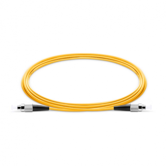
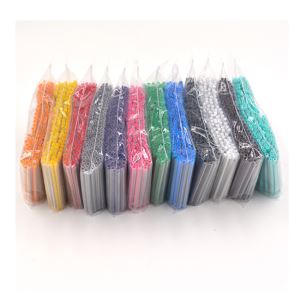
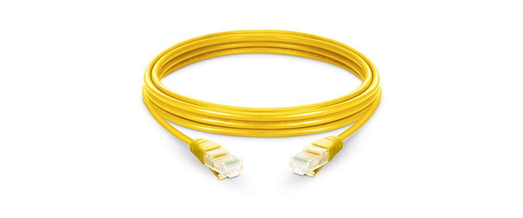
Cat5e Patch Cable
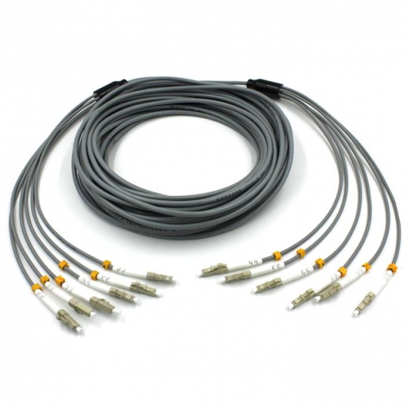
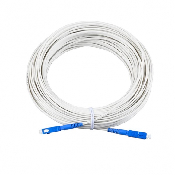
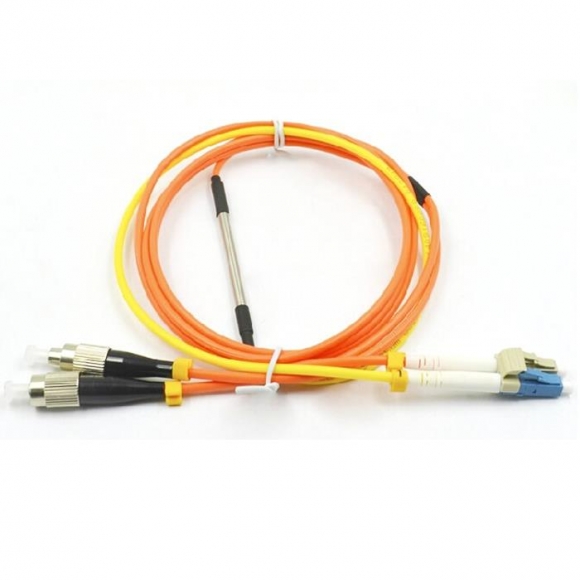
The cat5e patch cable is the basic component to connect end devices to patch panel ports and to connect the ports between two local patch panels. So when wiring the Cat5e patch panel, a big issue is the design and quality of the terminations of Cat5e patch cables. When choosing a suitable patch cable, booted and non-booted is two basic types of plug features. The booted cable is an ideal choice to protect the tab from breaking, and the non-booted is usually used for applications that don’t require frequent unplugging. we offer a full range of Cat5e patch cables available in a variety of length and color, including Snagless booted cable, non-booted cable, and retractable cable. Besides, we can also provide custom and OEM services for network patch cable. Customized jacket, connector types, length and colors of network patch cable are all available to you.
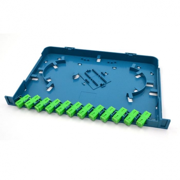
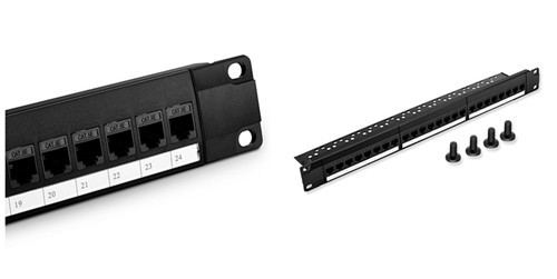
Cat5e Patch Panels
A copper patch panel is used in a local area network (LAN) as a mounted hardware assembly that contains ports to connect and manage incoming and outgoing Ethernet cables. It is compliant with TIA/EIA 568 industry specifications and features both T-568A and T-568B wiring configurations. These patch panels can maximize network performance and keep up with the growing changes in the network. Generally, Cat5e copper patch panels can be divided into shielded and unshielded patch panels, which are required to match with cable applications. Cat5e shielded patch panels are designed for high EMI (Electro Magnetic Interference) environments, while unshielded patch panels are designed for the place where has no high power electrical wires. Besides, there is also the difference in the configuration: punch down and feedthrough patch panel. Punch down types are available in Cat5e patch panel. On the front plate, RJ45 ports are used to directly connect Ethernet copper cable. All ports are numbered for easy identification. In the rear, it’s patch panel module with color markings for punching down Ethernet cable. Color-coded labels are designed for T568A and T568B wiring configurations. However, Cat5e feedthrough patch panel provides patching without punching down the wires to the ports. Each feedthrough patch panel has both RJ45 ports on the front and rear side. And ports on the front side are numbered for easy identification and installation. With feedthrough patch panel, the Ethernet patch cables can be inserted into the ports directly in an easy and fast way. So Cat5e feedthrough patch panel is quite suitable for high-density network system, which can protect cable and improve cable management efficiency. When choosing a suitable Cat5e patch panel, the priority is to clarify all of the different types. we offers the mentioned types of Cat5e patch panels available in 24 and 48-port sizes. The high-density panel design can be mounted to standard racks or cabinets, accommodate top, bottom or side cable entry, and also save valuable rack space. The following table shows the Cat5e patch panel from us
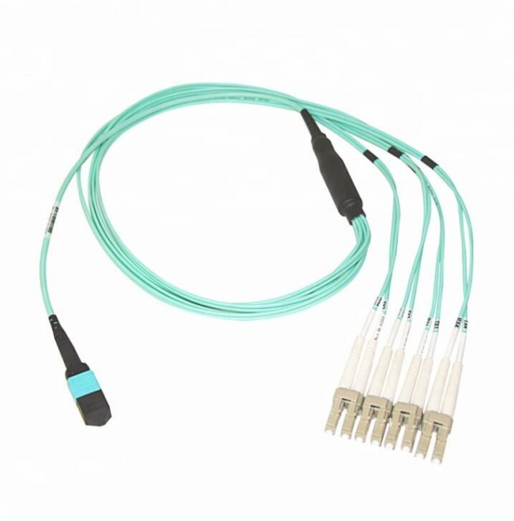
READ MORE ...High-density Fiber Optic Cabling Solutions – Push-Pull TAB and LC Uniboot Fiber Patch CablesCat5e Patch Panel Wiring Steps
Technical information:
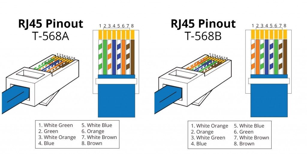
There are two wiring schemes: T568A and T568B. The difference between the two standards are only color, the way the pairs are grouped is still the same.
Required Tools:
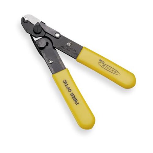
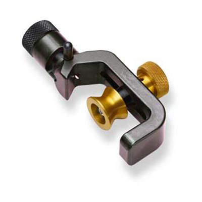
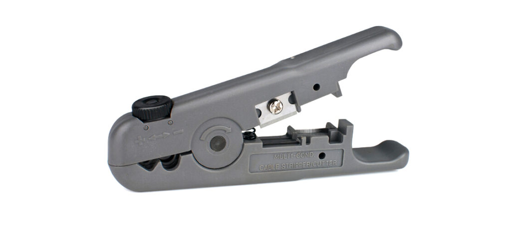
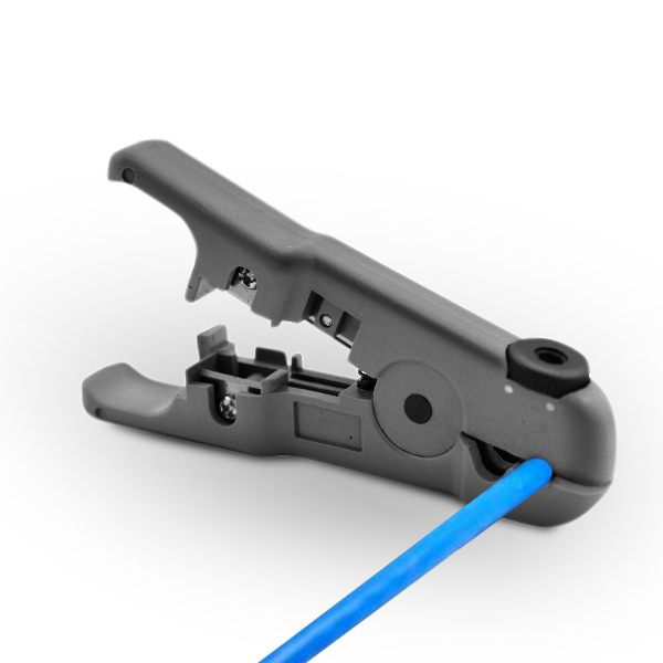
Cat5e Patch Panel Wiring Tool: Cable stripper
Stripping is the act of removing the protective outer jacket around network cables in preparation for installation of plugs or keystone jacks. It can help you speed up the process of performing fiber network maintenance work and avoid excessive network downtime. A stripping tool is an essential part in the process of wring Cat5e patch panel. we supplies a wide variety of cable strippers, including wire stripping knife tool, multifunctional network cable stripper, and diagonal cutting plier, which are all at a very competitive price to help you get the job done right.
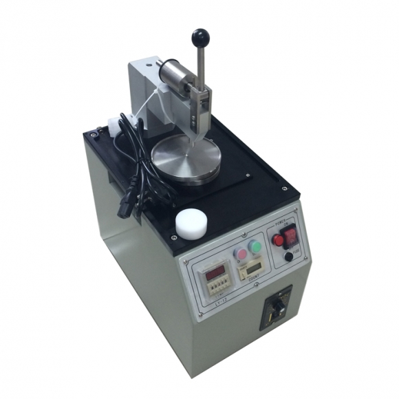
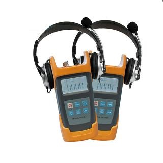
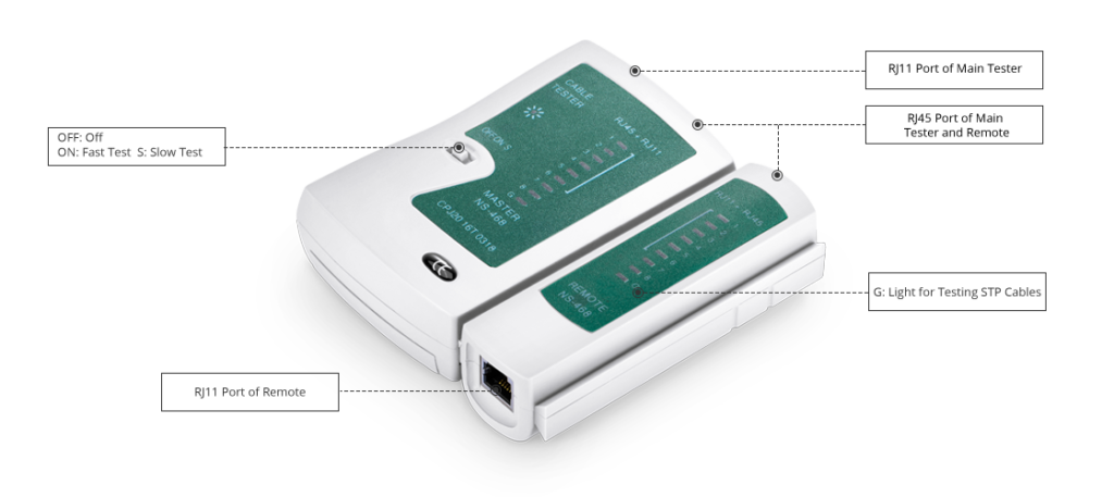
Cat5e Patch Panel Wiring Tool: Network cable tester
Cable tester is a tool to test whether a cable or wire is set up properly, connected to the appropriate source points, and if the communication strength between the source and destination is strong enough to serve its intended purpose. NS-468 is the key tool used in the wiring process of the Cat5e patch panel. It can test the Cat5e, Cat6, Cat6e cables and the coaxial cable as well as the telephone wire, etc. And it can also be used to test situations like the breaking at the set point, the short circuits, the gross pair wire, and the split pairs as well the reversed pair wire, etc.
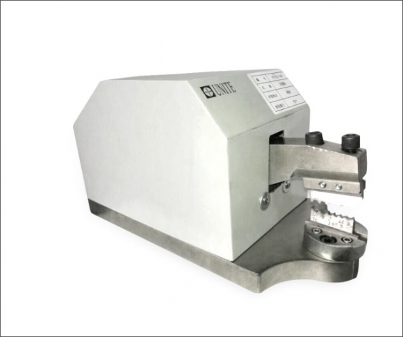
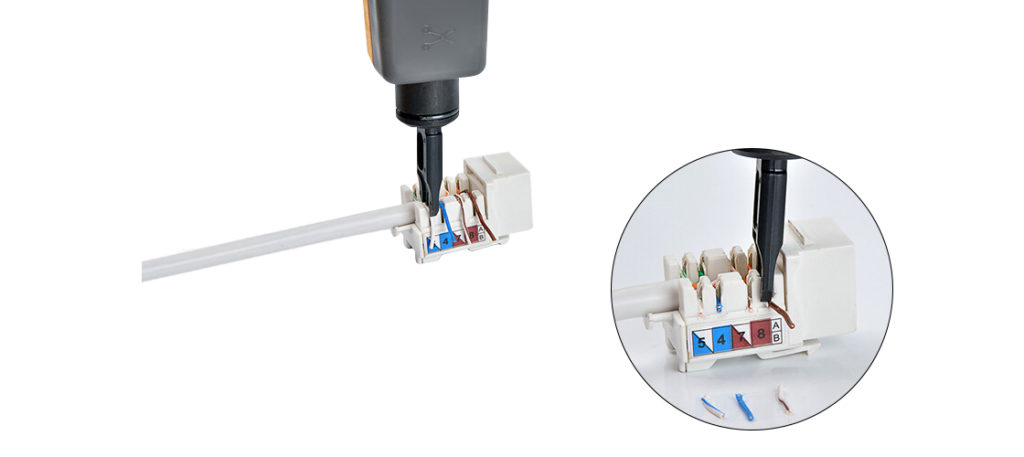
Cat5e Patch Panel Wiring Tool: 110 punch down tool
Punch down tool is a small hand tool used by telecommunication and network technicians. It is used for inserting the wire into insulation-displacement connectors on the punch down blocks, patch panels, keystone modules, and surface mount boxes. FPDT-X02 is a good choice to insert and cut cable terminations effortlessly.
READ MORE ...Plenum Cable vs Non-plenum Cable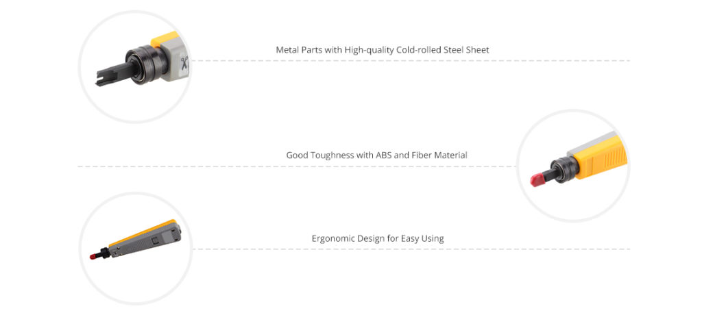
Cat5e Patch Panel Wiring Specified steps:
Step 1: Examine the 110-style punch down connectors on the back of the Cat5e patch panel.
The Cat5e patch panels should have 110 style insulation displacement connectors. It is necessary to acquire enough patch connectors on the patch panels to accommodate all of the incoming Ethernet cables.
Step 2: Remove the outer jacket from the end of each cable.
You should use the cable strippers to remove approximately 1 inch (25mm) of the outer jacket from the end of each cable, which ensures a nice clean fit into the patch panel without the risk of exposing too much cable and damaging it.
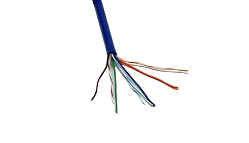
Step 3: Spread out the cable wires.
Once the outer jacket has been removed, you will see 4 twisted pairs of wires (a total of 8 wires) inside the Ethernet cable. The wires are color coded with 4 being solid colors, and 4 with a white stripe around the color. In order to successfully punch down the cables into the patch panel, you need to gently untwist the pairs and spread them out so that the 8 wires can be individually worked work with.
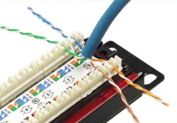
Step 4: Set the wires into the patch panel connectors.
Place all 8 wires into the 110 style connector of the patch panel in the patch panel outlet that is used to receive the incoming cables. You will see the color code labels on the patch panel, that indicates which wire is to be placed into which connector pin.(Note: There are two color patterns, T568A and T568B. Make sure to terminate both sides of the cable on the same pattern used.)
Step 5: Begin terminating each wire.
Use a 110 punch down tool to firmly press down on each wire so that it is grasped by both sets of teeth of the insulation displacement connector. Punch down tool is with a cutting edge, you can use it to cut the excess wire of the Ethernet cables during the pushing process.
Step 6. Mark the terminated incoming cables with a label.
This step is optional but recommended. Mark the terminated incoming cables with a label indicating where the cables are from with the room or floor numbers. It will help you locate the system problems precisely or handing the futures upgrading projects.
Step 7. Use a cable tester to assure that you correctly terminated all the wires.
Now you can plug a short patch cable from the desired port on the patch panel to the closely located hub or switch. The other end of the wire would be terminated at a wall socket.
- Customers Reviews
-
 (0)
(0) (0)
(0) (0)
(0) (0)
(0) (0)
(0)
* Delivery Time.
We need 1-2 days to process your order before shipping. There are two shipping methoed.
Fast Delivery: The delivery time for US, European countries the delivery will take 3-5 days.
Slow Delivery: The delivery time for US, European countries the delivery will take 7-15 days.
* Tracking information.
After we ship package, customer receive automatic email with tracking details.
* Lost Package Policy.
If a package did not arrive in 2 weeks after the shipping date, then this package is treated as Lost. In this case a new package will be shipped to the customer provided we are able to give the same items as those purchased by the customer. If we are not able to provide the same items to substitute the lost ones we will either propose to the customer similar items or refund their cost as it will be mutually agree with the customer. If one or more items neither the same nor similar are available to be shipped, the customer can request to cancel the order entirely, thus the total cost of the order including shipping and handling cost will be fully refunded.


