


- Description
- Reviews
- FAQs
Many electric utilities install fiber optic cables on their high voltage lines to satisfy their own internal communication needs and to gain additional revenues by leasing excess capacity to telecommunication network providers. Electric utilities have been using fiber-optic cables to provide a communications link between neighboring substations or between substations and their control desks. However, ADSS turned out to be a industry wide problem where surface deterioration lead to their failure. Investigations found the failure mechanisms. Recommended methods were published, based on the geometry and voltage levels. Utilities should review these recommendations hence these can help them optimize stringing positions for various towers and power line configurations.
Fiber optics can offer a unique solution to the ever-increasing demand for bandwidth because of their remarkable high capacity for carrying data and their immunity to electromagnetic interference. However, integrating fiber optic cables into high-voltage corridors poses some technical and safety-related challenges that relate to corona and arcing. When ADSS fiber-optic cables are installed improperly on high-voltage transmission lines, unexpected failures can destroy these high-speed and high-capacity communication channels.
General Information on Fiber Optics
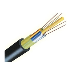
An optical fiber is a thin, long, transparent material (glass or plastic) that propagates light waves in order to transmit information.
Advantages:
- Light signals have low power consumption, convey signals over long distances without amplification
- Large bandwidth – large amount of data
- Easy installation – small dimension & low weight
- No EMI effect (Electro Magnetic Interference)
- Fit for digital signals
- Have immunity to RF interference
- Many fibers can be bundled in a single cable for a larger capacity
- Cables can be mounted on existing grid
Disadvantages:
- Optical to electrical conversion & vice versa is complicated
- Fragile, delicate and therefore relatively high cost
- Welding broken fibers, if at all, is difficult and problematic
Cable Types
Three types of fiber-optic cables are commercially available for installation in high-voltage lines:
- Optical Ground Wire (OPGW) is a cable encased within the ground wire. Used in transmission lines on ground conductors with the fiber-optic cable embedded inside. However, since the majority of HV and MV transmission lines have no lightning protection ground wires it is not frequently used. Moreover, OPGW besides being an expensive cable, installation requires long term outages
- Wrapped Round the Phase conductor or the ground wire (WRAP) is spiral wrapped cable around existing overhead ground conductors or in some cases, phase conductors. Winding the fiber-optic cable on the phase conductors of HV or MV is not possible because the conductor diameter is generally too small and of insufficient mechanical strength for the wind loading moreover, hot-line installation is very difficult
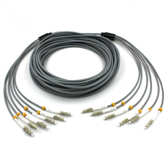
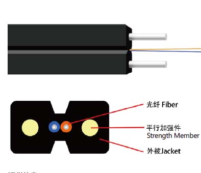
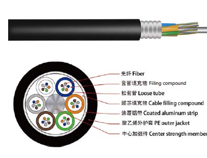
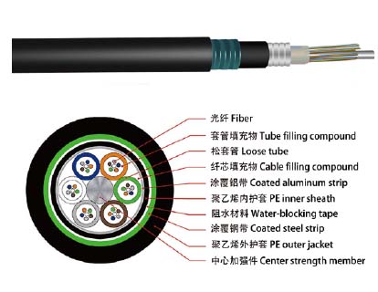
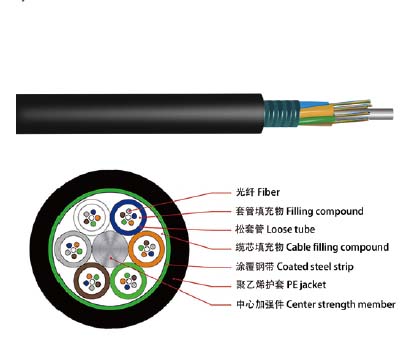
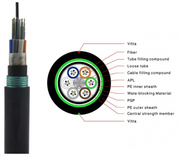
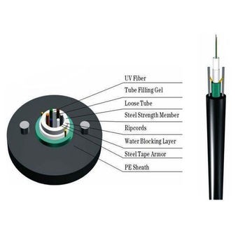
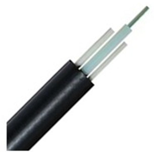
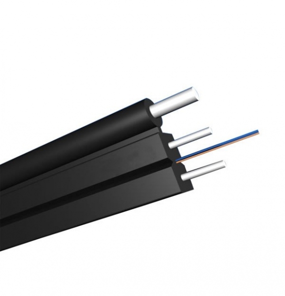
- All Dielectric Self Supporting (ADSS) the most frequently used cable. ADSS is self-supporting, has no metal components and can be installed on live lines without outages. ADSS has multiple fibers channels per cable. They have 2 design families: double jacket with a max of 576 single fibers for spans that are up to 6000 feet, or single jacket with a max of 144 single fibers for shorter spans.
ADSS INSTALLATION
ADSS is installed 10 ft to 20 ft (3m to 6m) below the phase conductors. Grounded armor rod assemblies support the fiber-optic cable at each supporting structure. Utilities have reported failures of ADSS installed on their high voltage lines. The high electric field on transmission lines generates continuous corona discharge at the end of supporting armor rods. This discharge leads to cable deterioration. In polluted environments, dry band arcing causes cable deterioration when fog or dew occasionally wet the cable. ADSS life expectancy on power lines depends on the following factors:
- Electrical
- Corona effect
- Dry-Band arcing
- Space potential effect
- Mechanical
- Span length and sag
- Tension on cables
- Environmental
- Wind velocity and Aeolian vibration
- Sheath composition for UV resistance (UV from the sun)
- Pollution & temperature
All Dielectric Self Supporting (ADSS) fiber optic cables are located in high electric fields. Their sheath can be subjected to dry band arcing and corona especially in highly polluted areas with little rainfall where there is regularly high conductivity precipitation on the cable and it is rarely cleaned by natural rainwater.cleaned by natural rainwater.
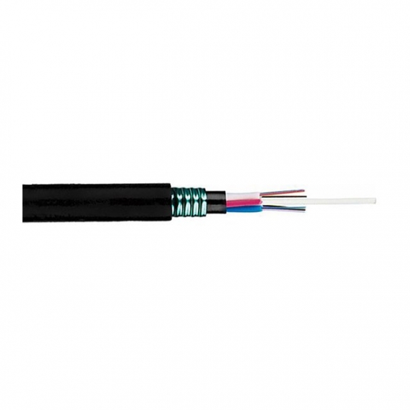
Corona or dry-band arcing puncture the cable sheath allowing water penetration leading to destruction of the aramide yarn and exposing the PBT tubes that contain the optical fibers. In more severe cases a massive reduction of mechanical strength can even lead to cable dropping.
Corona Effect
Corona discharge is expected in locations with local high electrical fields caused by sharp edges, for example, at the tips of armor-rod assemblies of transmission lines conductors. Armor rod assemblies are attached to transmission line structures, support cables, provide mechanical strength protecting them from bending and also ground the cables. Depending on the placement of the cable with respect to the high voltage conductors, the conductor’s voltage and the pollution on the cable surface can induce current to flow along the cable. This gives rise to corona, micro-sparking and dry band arcing, especially near the tower where the e-field is greatest. The local partial discharge processes involves the emission of UV and the creation of ozone and other acids, reagents that erode the galvanized conductors and the ADSS sheath.
Dry-band Arcing
Even though ADSS cables are electrically non-conductive, contamination that accumulates on their outer sheath can turn them into being conductive. When the layer of pollution gets unevenly wet it becomes semi-conductive. Most cases of failing ADSS occurred in highly polluted areas or in coastal areas. The wind from the sea drives saltwater droplets onto the fiber-optic-cable surface, covering the cable with a thin layer of salt. Fog or dew wets the pollution layer and forms a conductive layer on the cable surface. Capacitive coupling between the phase conductors and fiber-optic cable induces current along the wet pollution layer. This current dries the layer and forms small dry bands. The dry band interrupts the current and generates high voltage across the band. This voltage produces arcs. The heating effect of the arc extends the dry-band length, which stops the arcing. However, condensation and wind-driven saltwater from the sea wet the cable and re-initiate the arcing. Dry-band arcing is a periodic phenomenon that occurs when the cable is simultaneously wet and polluted.
The higher the contamination and moisture, the higher the induced current thus, in subtropical areas, dry-band arcing as well as corona are especially harmful due to the specific climate conditions: an eight- to nine-month dry period followed by a shorter rainy period in winter. The cable surface pollution layer after the dry period is hard and adhesive, and particularly thick in the regions nearing clamps causing a serious corona problem.
READ MORE ...How do you choose Fiber Optic patch cablesUtilities should look for tests procedures for evaluating ADSS fiber optic cables installed on overhead power lines. Organizations such as IEEE, WAPA, EPRI, BPA, Washington State University and others keep on studying this issue.
Overhead fiber optic cable systems have become a key factor in telecommunication networks used by operators and power utilities.
The key advantages of using overhead electricity distribution lines to carry cables providing broadband connectivity can be summarised in three distinct areas: speed, security, and cost.
● Speed: It is always much, much quicker to install fiber optic cable by attaching it to poles than it is to dig trenches to bury it underground. It is generally possible to install at least 1km of fiber optic cable a day on overhead power lines and up to 5km per day is possible in favorable circumstances.
● Security: Security is a key concern in any fiber optic cable installation. Cables have been installed on overhead power lines since the very early 1980s and have developed an excellent reputation for security and reliability over that time. Power utilities use these cables to carry critical communications for control of the electricity network. Fiber optic cables installed above ground are not subject to ‘dig-ups’ which is the biggest cause of cable damage. Cables that are installed as part of the electricity infrastructure are protected by the proximity of power conductors, which provide protection against theft and vandalism.
● Cost: The higher unit cost of aerial cables compared to underground cables is more than offset by the much lower cost of installation and therefore aerial cables have the lowest total cost. Aerial cables have much higher installation rates and so networks are built much more quickly, begin to provide services earlier and so have quicker returns on investment. Put another way, with reduced initial costs and earlier in-service dates, aerial cables have shorter payback times than underground networks.
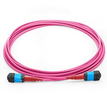
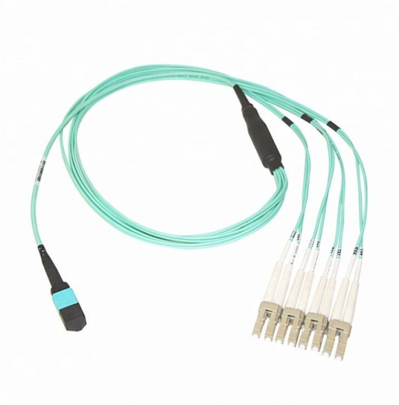
Sun Telecom provides a broad range of fiber optic cables for overhead cable networks:
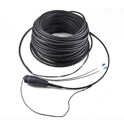
All Dielectric Self-supporting Aerial Cable (ADSS Cable)
On existing transmission lines, the preferable option is to install ADSS cables, being cost-effective. The installed ADSS is independent of power lines and provides an attractive solution in respect of maintenance of both power lines and fiber optic cables.
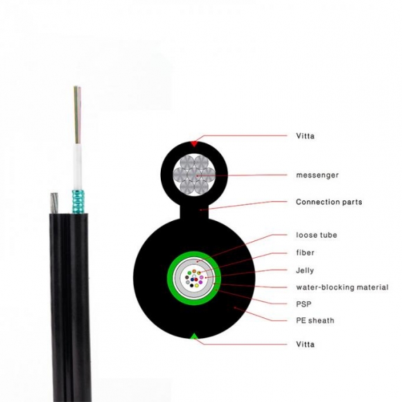
Optical Fiber Composite Overhead Ground Wire Cable (OPGW Cable)
OPGW cable is designed as a two function aerial conductor viz, a shield wire to take care of fault current and lightning strike, and integrated fiber optic unit taking on the function of communication. The OPGW has been found to be the best solution when installing as replacement of conventional earth wire on new transmission lines or when there is a need to change the old ground wire of existing line.
- Customers Reviews
-
 (0)
(0) (0)
(0) (0)
(0) (0)
(0) (0)
(0)
* Delivery Time.
We need 1-2 days to process your order before shipping. There are two shipping methoed.
Fast Delivery: The delivery time for US, European countries the delivery will take 3-5 days.
Slow Delivery: The delivery time for US, European countries the delivery will take 7-15 days.
* Tracking information.
After we ship package, customer receive automatic email with tracking details.
* Lost Package Policy.
If a package did not arrive in 2 weeks after the shipping date, then this package is treated as Lost. In this case a new package will be shipped to the customer provided we are able to give the same items as those purchased by the customer. If we are not able to provide the same items to substitute the lost ones we will either propose to the customer similar items or refund their cost as it will be mutually agree with the customer. If one or more items neither the same nor similar are available to be shipped, the customer can request to cancel the order entirely, thus the total cost of the order including shipping and handling cost will be fully refunded.

