


- Description
- Reviews
- FAQs
The optical transceiver (transmitter and receiver) used for optical-to-electrical conversion is a key component in optical communication systems. In a PON system, an optical transmitter and receiver at the optical line terminal (OLT) or optical network units (ONUs) are typically packaged together to form a bidirectional optical subassembly (BOSA).
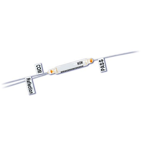
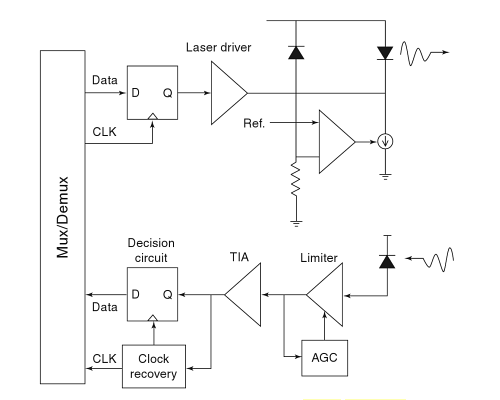
The figure below shows the architecture of optical transceiver for an OLT and ONUs. The transmitter optical subassembly (TOSA) consists of a semiconductor laser (Fabry-Perot laser or DFB laser) and a laser driver. The receiver optical subassembly (ROSA) includes a photodiode (PIN or APD), a transimpedance amplifier, a limiting amplifier, and a clock and data recovery circuit. In addition to TOSA and ROSA, a duplex or tripex (WDM filter) is used to separate upstream and downstream wavelengths. The duplex or triplex is usually a thin-film filter, but optical filters (e.g., Bragg grating or a Mach-Zehnder interferometer) based on planar light-wave circuits are becoming a preferred option, as plannar light-wave circuits are more compact, more reliable, and easier to assemble with TOSA and ROSA. As TDM PONs are being deployed on a large scale, significant effort has been put into designing an optical transceiver with improved performance, lower cost, and better reliability. The key challenges in developing optical transceiver for FTTx applications are a higher level of integration, cost-effective packaging, and burst-mode optical transmission technologies in the upstream link. For integration and packaging, optical transceivers are evolving toward plannar light-wave cirsuits and monolithic photonic integrated circuits.
Burst-Mode Optical Transmission
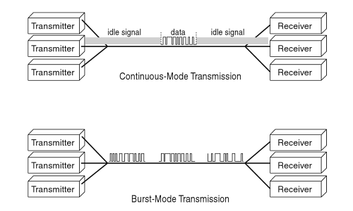
In a TDM PON system, all the users share the same fiber infrastructure from an OLT to the distribution node. In the downsream direction, data packets are broadcast to all ONUs. OLT transmitters and ONU receivers operate in a continuous mode, where synchronization is maintained at all times. Even if there are no data to send to ONUs, the OLT transmitter has to transmit idle bit patterns so that the ONUs’ receiver can retrieve the clock continuously from the downstream signal. However, in the upstream direction, all the users have to be avoided in the upstream transmission, so at any given time, only one packet (from one ONU) is allowed to reach the central office. The OLT coordinates the upstream transmission and schedules the transmission time for each ONU. When an ONU wants to send data to the OLT, it transmits a burst of data in the time assigned by the OLT and then turns off its transmitter completely to avoid interfering with other ONUs’ upstream transmission. Bursts of data from different ONUs following each other to the receiver at the central office are separated by a certain guard time. This type of transmission is called burst-mode transmission.
READ MORE ...What is an Optical Transceiver moduleHere is a figure that compares the data formats of continuous- and burst-mode transmission. Burst-mode transmitter at each ONU and a burst-mode receiver at the central office are indispensable. A burst-mode receiver at rhe central office is required to have various affordable input ranges and fast clock locking times. On the other hand, a burst-mode transmitter, located on the user side, has to show fast turn-on time as well as good power suppression during an idle state. Designing high-speed burst-mode optical transceiver is necessary and challenging when deploying passive optical networks.
Burst-Mode Laser Drivers
A burst-mode transmitter has to show fast turn-on time as well as good power suppression. The design challenges for burst-mode laser/modulator drivers are rise and fall times and automatic power control. Conventional driver circuits are designed to maintain a constant bias current and voltage. However, good optical power suppression in the idle state requires that the bias be turned off quickly. Driver circuits have to be designed to have short turn-on/off performance. For automatic power control, conventional circuits often use slow monitor photodiode and/or analog filters to average the signal and an analog control loop to analog control loops. It is necessary to monitor optical output sampled at appropriate points in burst waveform.
Burst-Mode Receivers
Conventional optical receivers cannot be used for burst-mode detection because they are not able instantaneously to handle various packets arriving with large differences in optical power and phase alignment. It is therefore necessary to design receivers that can adapt to the variation in optical power and phase alignment on a packet-by-packet basis. The design challenges for burst-mode receivers are dynamic sensitivity recovery, level recovery, and fast clock recovery.
READ MORE ...Fiber Optic Cables vs Copper CablesWhen a weak burst follows a strong burst, it is difficult to detect the weak signal. Dynamic sensitivity recovery is necessary for detection of the weak signal. The recovery of the weak burst is limited by photodiode carrier transport effects, amplifier slew and charging rates, and unintentional automatic gain control effects.
For level recovery, a burst-mode receiver can be designed with a feedback or feedforward structure. For the feedback design, a differential input/output transimpedance amplifier and peak detection circuit form a feedback loop, whereas in the feedforward design, the signal from the preamplifier is feedforward into a peak detection circuitry. Both designs have been implemented in practice. A feedback structure enables the receiver to work more reliably, but a different input/output preamplifier is needed. A feedforward receiver has a faster response time and a conventional dccoupled preamplifier can be used, but the circuitry needs to be designed carefully to prevent oscillation in the reveiver. Level recovery circuits with simple and robust design and good performance are still an open issue that requires further investigation.
SUNMA is an OEM manufacturer of fiber transceiver modules. We provide optical transceiver not only for TDM PONs, we also offer compatiable transceiver modules worldwide. Welcome to visit our website where you can find the modules you want to buy. Our optical modules can be compatiable with all brands, such as the SFP modules: GLC-LH-SM Cisco, HP J4858A, JX-SFP-1FE-FX (Juniper compatiable), etc..
- Customers Reviews
-
 (0)
(0) (0)
(0) (0)
(0) (0)
(0) (0)
(0)
* Delivery Time.
We need 1-2 days to process your order before shipping. There are two shipping methoed.
Fast Delivery: The delivery time for US, European countries the delivery will take 3-5 days.
Slow Delivery: The delivery time for US, European countries the delivery will take 7-15 days.
* Tracking information.
After we ship package, customer receive automatic email with tracking details.
* Lost Package Policy.
If a package did not arrive in 2 weeks after the shipping date, then this package is treated as Lost. In this case a new package will be shipped to the customer provided we are able to give the same items as those purchased by the customer. If we are not able to provide the same items to substitute the lost ones we will either propose to the customer similar items or refund their cost as it will be mutually agree with the customer. If one or more items neither the same nor similar are available to be shipped, the customer can request to cancel the order entirely, thus the total cost of the order including shipping and handling cost will be fully refunded.


