


- Description
- Reviews
- FAQs
In any installation, it is essential to ensure that the optical transmitter at one end is connected to the optical receiver at the other. This matching of the transmit signal (Tx) to the receive equipment (Rx) at both ends of the fiber optic link is referred to as polarity. For traditional cabling systems using single fiber connectors, such as SC or LC, maintaining polarity is as simple as insuring that the A side of one connector pair matches to the B side of the other connector pair in any patch cord or permanent link. But for the high-density MTP/MPO array connectivity systems, it have their own requirements for maintaining proper polarity. This article will illustrate MTP/MPO polarity methods for duplex signals.
MTP/MPO Array Connector Structure
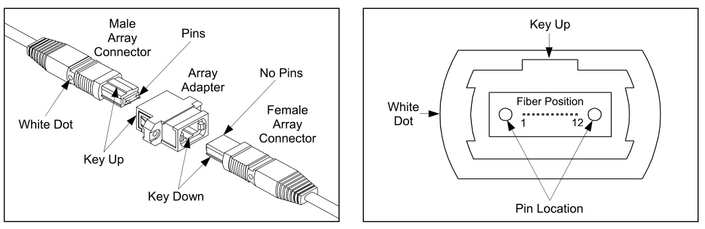
Array connectors terminate multiple fibers in a single high-density interface. There are 4, 6, 8, and 12-fiber array connectors. And 12-fiber array connectors are the most common. As shown in the following picture, array connectors are pin and socket connectors, which require a male side and a female side. Moreover, each MTP connector has a key on one side of the connector body. When the key sits on top, this is referred to as the key up position. In this orientation, each of fiber holes in the connector is numbered in sequence from left to right. We will refer to these connector holes as positions, or P1, P2, etc. Besides, each connector is additionally marked with a white dot on the connector body to designate the position 1 side of the connector when it is plugged in.
MTP/MPO Adapter Keying Options
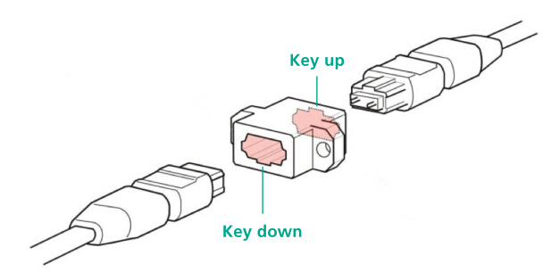
MTP/MPO adapters contain an asymmetrical housing including an inverted key to achieve the appropriate fiber polarity. On type A adapters, the keys are inverted to ensure that the fiber at position 1 is connected to position 1 in the MTP/MPO cable connector at the opposing end.
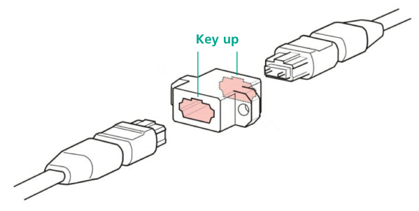
On type B adapters, both keys are oriented facing up in order that both MTP/MPO cable connectors are mated “key up” wise. The fiber at position 1 is connected to position 12 in the MTP/MPO connector at the opposing end.
Three Polarity Methods for MTP/MPO Systems
READ MORE ...build a 1000BASE-X fiber optic segmentThree different methods for maintaining polarity in pre-terminated MTP systems are defined in TIA/EIA-568-B.1-7. These three methods define installation and polarity management practices, and provide guidance in the deployment of these types of fiber array links. Once a method is chosen, these practices must be put into place to insure proper signaling throughout the installation.
- Method A
Method A employs “key up to key down” adapters to connect the array connectors. As shown below, this method maintains registration of Fiber 1 throughout the optical circuit. Fiber 1 in the near end cassette mates to Fiber 1 in the trunk cable assembly, which mates to Fiber 1 in the remote cassette. The fiber circuit is completed by utilizing one flipped patch cord, either at the beginning or end of the permanent link, to insure proper transceiver orientation.
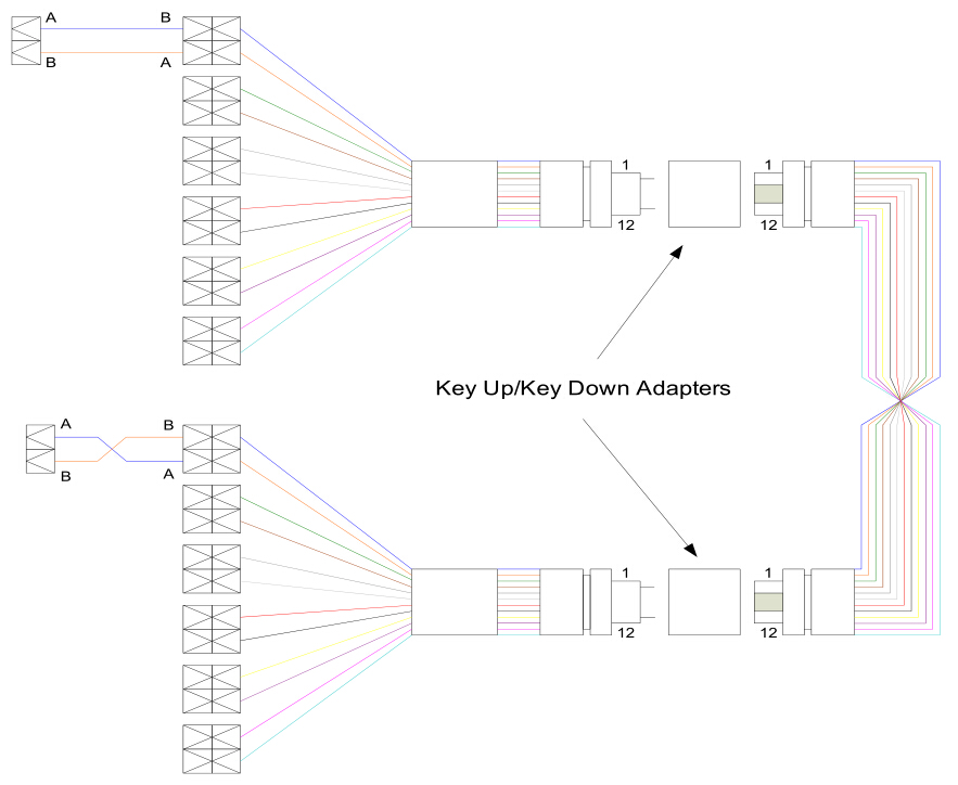
Method A provides the simplest deployment, and works for single-mode and multimode channels, as well as can easily support network extensions.
- Method B
Method B uses “key up to key up” adapters. The fiber circuit is completed by utilizing straight patch cords at the beginning and end of the link, and all of the array connectors are mated “key up to key up”. This type of array mating results in an inversion, meaning that Fiber 1 is mated with Fiber 12, Fiber 2 is mated with Fiber 11, etc. To ensure proper transceiver operation with this configuration, one of the cassettes needs to be physically inverted internally so Fiber 12 is mated with Fiber 1 at the end of the link.
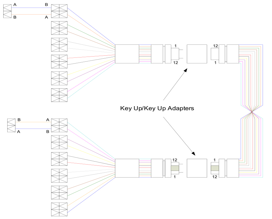
This method requires a more in-depth planning stage in order to properly manage the polarity of the links, and to identify where the actual inversions need to occur. It also requires two separate cassettes or special labeling and management of the cassettes on one end are flipped. Moreover, it does not support single-mode with standards compliant connector endfaces.
- Method C
Method C uses “key up to key down” adapters. The fiber circuit is completed by utilizing straight patch cords at the beginning and end of the link, and the same cassettes as in Method A. The difference between this method and Method A is that the flip does not happen in the end patch cords but in the array cable itself.
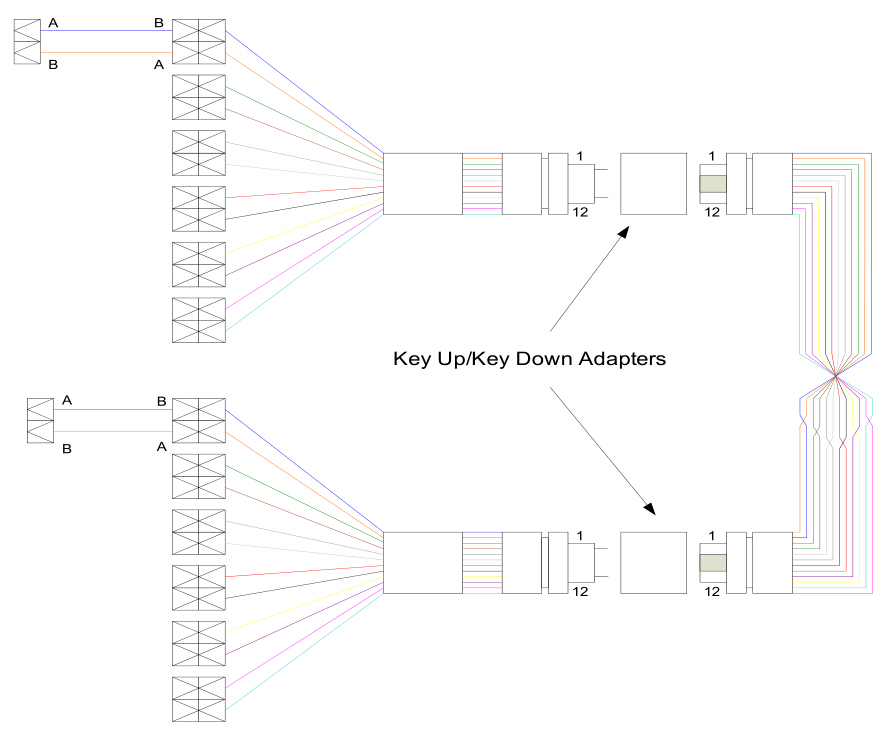
This method requires a more in-depth planning stage in order to properly manage the polarity of the links, and to identify where the actual flipped array cord is placed in the link. An additional drawback to this method is that if this link was to be extended, a straight array cord as used in Method A would need to be used to revert the polarity back to straight array polarity condition. In other words, unflip the array cable.
Summary
Three different polarity methods within array type fiber links are discussed in this article. And each of them has different features. Method A is recommended due to its simple cable manageability by utilizing one-for-one configuration throughout the link.
- Customers Reviews
-
 (0)
(0) (0)
(0) (0)
(0) (0)
(0) (0)
(0)
* Delivery Time.
We need 1-2 days to process your order before shipping. There are two shipping methoed.
Fast Delivery: The delivery time for US, European countries the delivery will take 3-5 days.
Slow Delivery: The delivery time for US, European countries the delivery will take 7-15 days.
* Tracking information.
After we ship package, customer receive automatic email with tracking details.
* Lost Package Policy.
If a package did not arrive in 2 weeks after the shipping date, then this package is treated as Lost. In this case a new package will be shipped to the customer provided we are able to give the same items as those purchased by the customer. If we are not able to provide the same items to substitute the lost ones we will either propose to the customer similar items or refund their cost as it will be mutually agree with the customer. If one or more items neither the same nor similar are available to be shipped, the customer can request to cancel the order entirely, thus the total cost of the order including shipping and handling cost will be fully refunded.


